I was asked if I could fix a broken LCD on a Samsung Galaxy S4….

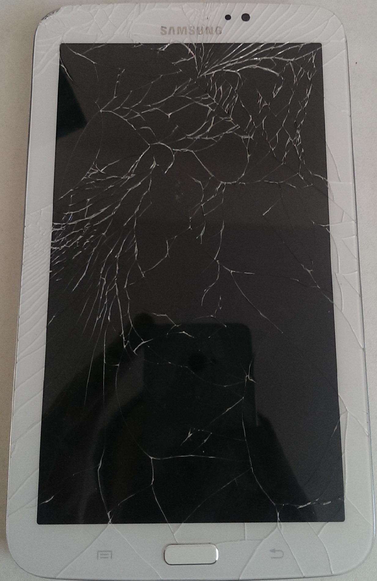
Broken LCD

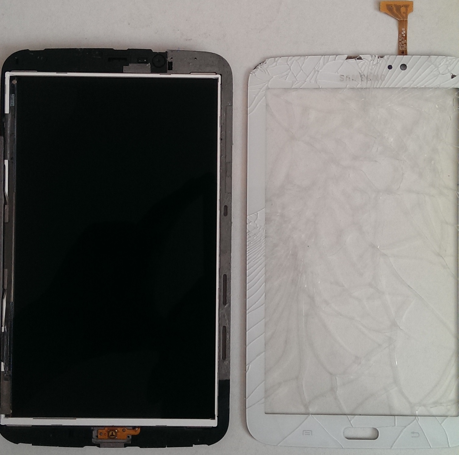
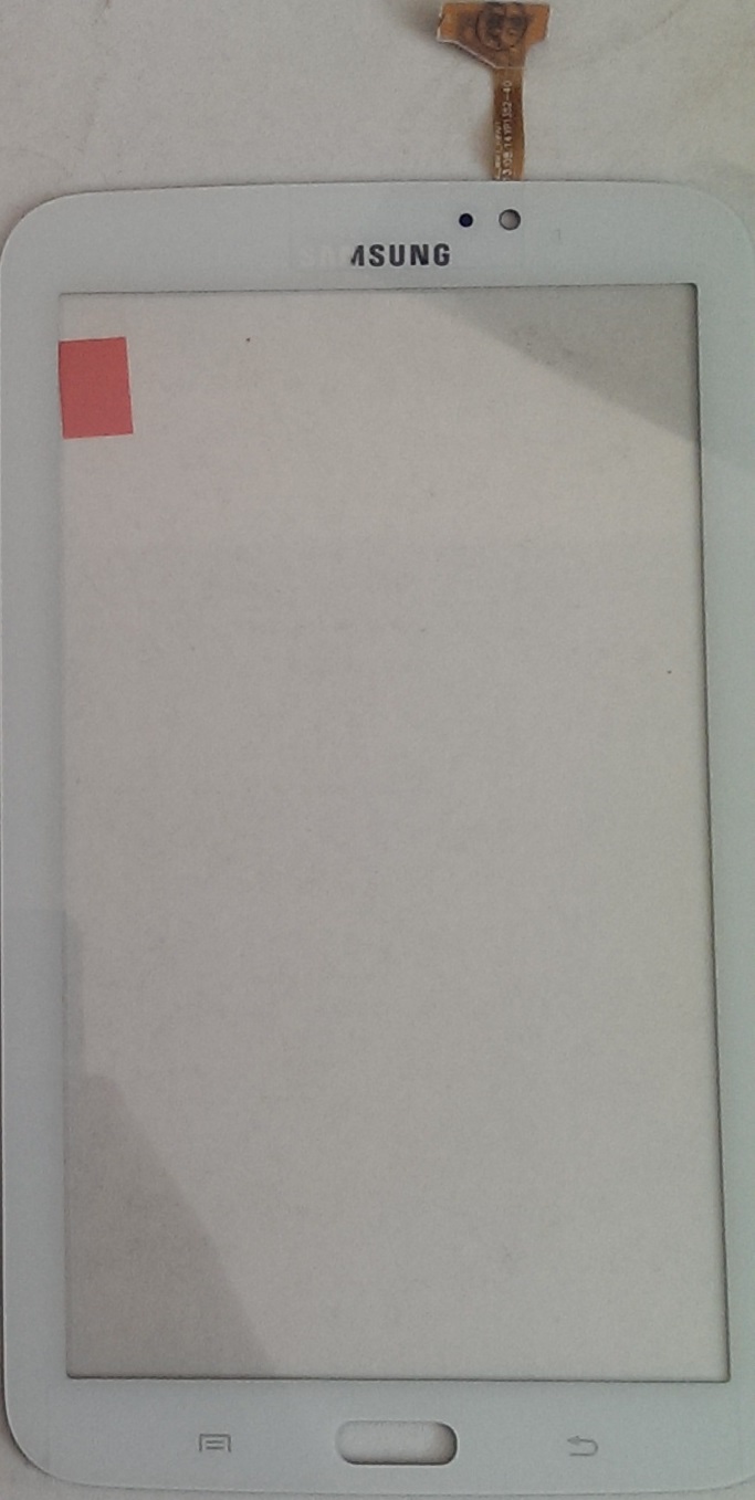
Front and rear view of new screen
This phone was dropped on tiles and it landed on the top right hand corner which resulted in a dead LCD but no broken glass which i thought was a bit unusual.
I started this project as I do with all other mobile devices, which is remove the rear cover, battery, sim card and SD card. Once all these are removed i then proceed with the dismantling of the device.
Due to the fact that the LCD was broken I had to order a complete replacement which included the front glass, LCD, digitizer and the plastic bezel.

Screw placements and speaker enclosure

Midframe removed
I began removing the nine 4.0 mm Philips screws which secure the midframe and speaker enclosure to the display assembly. Then starting on the volume side of the phone, I inserted the plastic opening tool between the chrome bezel around the display glass and the larger chrome border piece. (Look for the seam between the two). I continued sliding the opening tool along the seam, separating the plastic clips as I went. Once i had completed a full circle I was able to remove the midframe from the display assembly.

USB Logic board
I then began to remove the USB board which is located at the bottom of the phone. There is a metal bracket that covers the USB port which needs to be lifted on one side to remove it from its post. With the bracket removed, the soft button cable and the antenna needed to be removed before the USB board could be removed from the assembly. I had to be very careful because the board is very thin and it is stuck to the assembly, so a small amount of heat was needed to soften the glue so that it could be removed. I then quickly transfer the Logic board over to the new assembly before the glue got a chance to harden.

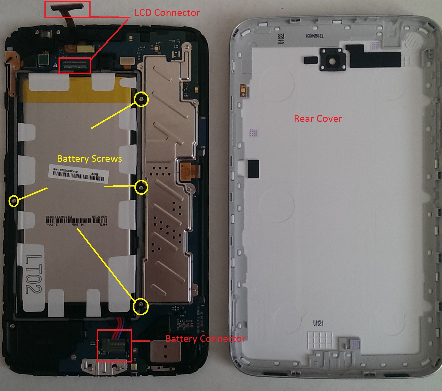
Location of motherboard connectors and screw.
Then using the flat end of a spudger i began removing all the motherboard connectors for various components. These included the front facing camera, earpiece speaker, headphone jack and display/digitizer, all of which are shown on the diagram to the right of this paragraph. There was also one 2.4 mm Phillips screw that needed to be removed before the motherboard was completely free.

Headphone jack
With the motherboard safely removed there was four more components to be removed and transferred to the new assembly. Starting with the headphone jack assembly, I removed the single 2.4 mm Philips screw that was holding it in place and it came out no problem. Next it was onto the front facing camera and earpiece speaker assembly both of which were held in place with a single metal bracket and a 2.4 mm screw. With the screw removed the bracket was easily lifted and both of the components were removed and transferred. The final part was the vibrator module which was held in position with adhesive and was removed without any heat with a spludger tool.

Component locations

Fully working phone
With all the components removed and transferred to the new assembly, I could then fully reassemble the device and after a full system test, everything worked….